DC Motors |
| |
| BRUSH-TYPE
DC MOTOR
ACTION |
When a current-carrying conductor is
placed in, and at a right angle to, a magnetic
field, it will experience a force perpendicular
to the field and to itself. The direction
of the force in relation to the field and
current is shown in the figure below a and b. The
force on this conductor is proportional to
the flux density, current and the length of
the conductor.
Using the above principle, we can explain
the motor action of a simple single
loop armature as shown in the figure below (c),
where DC current enters the right side of
the loop and exits the left. The resultant
forces acting on the single loop armature
generate a clockwise torque. However, the
torque diminishes to zero as the plane of the armature coil becomes perpendicular
to the field as shown in the figure below (d).
|
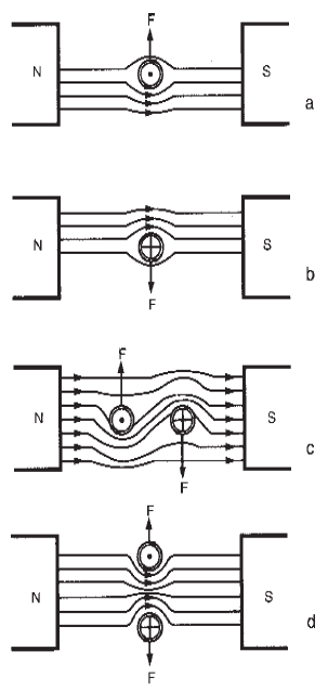 |
Upward and down
ward forces created by interaction of
field and armature flux. |
|
Commutation: |
In order to continue
the clockwise motion of our simple single
loop armature, we need a commutator
arrangement as shown below (a). As the
coil becomes perpendicular to the magnetic
field, the direction of current in the coil
reverses, causing the forces acting on the
coil to switch their direction. The coil then
continues to rotate in a clockwise direction.
The torque produced on the armature is
proportional to the sine of the angle between
the magnetic field and the plane of
the rotating coil. The torque will produce a
ripple type waveform as shown below (b). This figure shows that the resulting
torque reaches zero at the two vertical
positions during the armature (loop) rotation.
This simple motor relies on the inertia
of the armature to carry it through the zero
torque points to continue its rotation.
To eliminate this effect and keep a level
of torque always at some point above zero.
a four-segment commutator and two
armature coils may be used (see figure below - c).
This arrangement staggers forces to keep
the torque at an acceptable level. The
torque/position curve will then look like
the figure below (d). The more segments added to
the coils and corresponding commutator
armature, the closer the torque curve will
approximate a straight line characteristic.
See the figure below (e and f). |
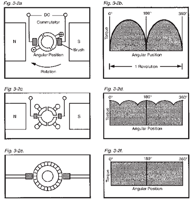 |
Relationship of commutator segments and torque:
a) two-segment commutator,
b) two-segment commutator torque curve,
c) four-segment commutator,
d) four-segment
commutator torque curve,
e) 32-segment commutator, and f) 32-segment commutator
torque curve. |
|
| The figure below shows the position of a commutator
in relation to the armature coils of
a typical DC motor. |
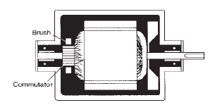 |
Commutator and brush position
in a typical DC motor design. |
|
Counter emf and Armature
Current: |
| When a DC armature is rotating
in a magnetic field, there is an induced
voltage produced in the armature which
takes the form of an opposing or counter electromotive
force (cemf). When the flux
field is held constant, this voltage is proportional
to the armature speed. Motor
action will continue as long as the voltage
supplied to the commutator is greater than
the cemf. The cemf limits the current flowing
in the armature according to the
formula: |
 |
| where V is the source voltage, I is the
armature current and R is the armature
resistance. It is inherent that the current in
the armature is proportional to the load or
torque produced. The current increases
with an increasing load until the motor
stalls, at which point the cemf is equal to
zero. |
Speed Control: |
The speed of a
DC motor is easily controlled by adjusting the voltage either in the field or armature or
a combination of both. This can be accomplished
by means of controls, variable
resistors and other devices.
Having briefly reviewed the fundamental
operation of commutator motors, we will
now consider each electrical type
individually. |
| |
| BRUSH-TYPE
DC MOTORS |
| |
| Series Wound |
Features: |
- Continuous or short time duty
- AC or DC power supply
- Usually unidirectional reversibility
- Speed varying with load
- Starting torque 175% and up of rated
torque
- High starting current
|
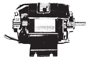
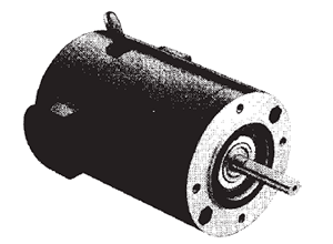
Design and Operation: |
Series
wound motors are among the most popular
of fractional and sub fractional hp motor
types. Capable of operation on either AC
or DC power supplies, series motors deliver
high motor speed, high starting torque
and wide speed capability, making them
ideal drives for a variety of applications.
See figure below. |
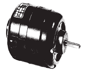 |
Series wound motor. |
|
The armature and field of a series motor
are connected in series with respect to the line. This feature allows series motors to be
operated from either AC or DC supplies
between 0 and 60 Hz. Because of their
“dual” capability, series motors are often
called “universal.” The performance difference
of a universal motor between 50 and
60 Hz is generally negligible. It should not
be assumed, however, that all series motors
are universal. Some may be optimized
for a particular power supply, and perform
poorly or fail prematurely if operated on a
power supply substantially different from
that specified on their nameplates.
Actually, no universal motor has the
same performance on both AC and DC.
Usually, the motor will run slower on AC
than on DC because the windings exhibit a
higher impedance when operated on an
AC supply. The speed difference is most
apparent with higher loads. Sometimes the
AC vs. DC speeds can be more closely
matched if a properly specified resistor is
placed in series with the motor when operated
on DC.
At lighter loads, an opposite speed relationship
may occur. Since the effective field
strength is lower on AC, the motor may
run faster. |
Advantages: |
In addition to their
versatility, series wound motors have the
highest horsepower per pound and per
dollar of any motor that operates directly
from standard single-phase AC power.
This factor accounts, in part, for the popularity
of series motors in household appliances
and power tools. The economics are
closely related to the inherent high speeds
of series motors. For example, a typical
AC induction motor rated at 1/10 hp (75
watts) at 1725 RPM weighs approximately
15 lbs. (67 newton's). A series universal
motor rated at 1/10 hp (75 watts) and
10,000 RPM can weigh under 4 lbs. (18
newton's).
Although there is a dramatic savings in
weight and cost per hp delivered, there are other aspects to the comparison:
- At the stated rating point in our foregoing
example, the torque of the induction
motor will be 58 oz-in. (410 mN-m),
compared with 10 oz-in. (71 mN-m)
for the series motor.
- The induction motor will have much
better speed regulation (less change in
speed with variations in load).
- The induction motor will be significantly
quieter because of its lower speed and
absence of commutating brushes.
- The induction motor will not have the
maintenance and service life considerations
associated with brush commutation.
|
In spite of these differences, series motors
are uniquely suited to a variety of applications.
In particular, series motors are
the only small motors capable of more than
3600 RPM operating directly from a single-
phase (60 Hz) AC power supply.
Also, the series motor will provide higher
starting torque than any other motor of
equivalent physical size operated from similar
power supplies. Used as a DC motor,
the series design is practical up to about
the 5" diameter size range. Above that, PM
and shunt-wound motors become practical
in a cost/performance trade-off.
Although series motors are usually supplied
as unidirectional (to obtain greater
efficiency and brush life) bidirectional series
motors can also be produced. One method
accomplishing this is a three-wire design
which can be reversed with a simple single
pole/double throw (SPDT) switch. However,
for this arrangement, a split or double
field winding is required, reducing the available
hp in a given frame.
An alternative to the three-wire method
is the four-wire series motor which is made
reversible by transposing the armature
leads, usually with a double pole/double throw (DPDT) switch. With reversible
series wound motors, the application must
be able to tolerate some variations in speed
between one direction and the other, due
mainly to inherent differences in commutation
until the brushes seat adequately in
each direction.
In addition to the advantages discussed
above, series motor speed can be adjusted
over a broad range by using a rheostat, an
adjustable autotransformer or an electronic
control. With the application of a mechanical
governor attached to the motor shaft, a
series motor can also provide a constant
speed over a wide torque range.
The no-load and operating speeds of
series motors are usually quite high. No load
speeds in excess of 15,000 RPM are
common and are limited only by the motor’s
own friction and winding characteristics.
Normal operating speeds are from
4000 to 10,000 RPM. The excellent
forced ventilation made possible at these
speeds helps to yield much higher horsepower
ratings than “common” induction
motors operating at 1725 to 3450 RPM. |
Disadvantages: |
A series motor
inherently provides poor speed regulation
and is classified as having a varying speed
characteristic. This means that the speed
will decrease with an increase in load and
increase with a decrease in load. The
amount of change will depend upon the
particular motor design. Speed changes are
more pronounced because the armature
and field are connected in series.
As the load is increased, the motor must
slow down to let more current flow to support
the load. This increase in current,
however, increases the strength of the field,
and thus the counter emf, which has a limiting
effect on current build-up. The result is
a further decrease in speed to compensate
for this change. However, the simultaneous
change in field and armature strength cause
the two to always be matched or balanced resulting in the excellent starting torque
characteristic of the series motor.
Although high speed is often a significant
advantage, it does not come without a
“price.” Specifically, bearing and brush life
are affected by high speed (household appliance
series motors typically have a brush
life of 200 to 1200 hours, depending on
the type of appliance). Centrifugal forces
must also be analyzed to prevent the destructive
effects of imbalance at high
speeds. These factors generally limit series
motors to intermittent duty applications.
However, series motors have been successfully
applied in many continuous duty
applications where operating conditions are
favorable, or where the nature of the application
provides for a moderate amount of
servicing. |
Cautions: |
Because of the steepness
of the speed/torque curve near the no-load
point, operation at or near no-load is usually
discouraged. See figure below. If consistent
performance between motors or even
in the same motor is desired, series motors
should be operated at some load value
beyond this point. The slope of the speed/
torque curve, along with the point of peak efficiency, can be altered slightly by the
motor manufacturer to suit specific
applications.
An additional caution-series motors
designed and built for one direction
of rotation should never be reversed
(extremely poor brush life and
performance can be expected). |
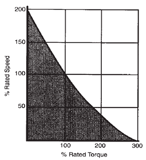 |
Typical characteristic curve for
a series type (universal) motor. |
|
| |
| Shunt-Wound |
Features: |
- Continuous duty
- DC power supply
- Reversibility at rest or during rotation
- Relatively constant and adjustable speed
- Starting torque 125% to 200% of rated
torque
- Normal starting current
|
Design and Operation: |
One of
the earliest and most versatile types of DC
motors, the shunt-wound design has always
enjoyed considerable popularity as
an excellent electrically adjustable, relatively
constant speed drive. With solid state
control circuitry and its inherent relatively
constant speed characteristics, the shunt wound
DC motor is a valuable companion
to advanced SCR (Silicon Controlled Rectifier)
controls. See figure below. |
 |
Shunt-wound motor. |
|
| The shunt-wound DC motor has both a
wound field and armature with spring-loaded
brushes applying power directly to the
armature by means of a segmented commutator.
The term “shunt” is derived from
the connection of the field and armature in
parallel (shunt) across the power supply.
See figure below. The field and armature may
also be separately excited from two independent
sources. This allows changes in
armature voltage to vary the speed while
still maintaining a constant field voltage. |
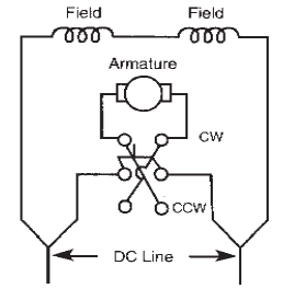 |
typical shunt wound
motor wiring diagram |
|
Advantages: |
The shunt motor inherently
provides good speed regulation (changes in
load only slightly affect speed within its
rated torque range).
For example, a 1/4 hp shunt motor operating
at a rated speed of 1725 RPM will
generally not vary in speed from no-load to full load by more than 15%. With modern
feedback-type controls, the speed regulation
can be even further improved to ±1%
or less over a defined speed range, without
an add-on tachometer. Tight control over a
wider speed range may require sacrifices in
regulation to compensate for the wide
speed range feature. A tachometer, feedback
or closed-loop control may also be
needed.
The most common means of controlling
shunt motors is the adjustment of armature
voltage while maintaining constant field
voltage. Armature voltage control is normally
used to decrease the motor speed
below its base speed. Regulation and starting
torque are generally not affected, except
at the very lowest speeds. A totally
enclosed shunt motor can be designed to
operate at rated torque down to zero RPM
without developing excessive temperatures.
Another method, field weakening, may
also be used to vary motor speed. It is,
however, usually used only to increase the
motor speed above its base speed and is
not often recommended unless the load is
decreased to maintain a constant horsepower
output. In addition, the percent of
regulation is increased and the starting
torque decreased with the field weakening
method.
Normal NEMA* speed ratings (base
speed) for shunt motors operated from
electronic controls are 1140, 1725, 2500
and 3450 RPM, but a shunt motor can be
wound to operate at any intermediate
speed for special purpose applications.
This same flexibility, within limits, also applies
to shunt motor voltage ratings.
Shunt designs are reversible at rest or
during rotation by simply reversing the armature
or the field voltage. Because of the
high inductance of the field circuit, reversing
the armature is the preferred method.
*NEMA is the national Electrical Manufacturers Association. |
Disadvantages: |
| If the shunt-wound
motor is operated from a fixed voltage
supply, a decrease in speed will occur as
the motor is loaded. The decreasing speed
with increased load tends to be linear over
a range in which the magnetic characteristics
are linear. As load is increased, further
saturation begins to occur, resulting in what
is commonly known as armature reaction
and the resultant abrupt drop in speed, as
shown in the figure below. The speed also increases
linearly with increasing armature
voltage, making the shunt-wound design
valuable as an adjustable speed motor. The
fact that speed varies proportionally with
armature voltage makes it possible to vary
speed over a wide range with electronic
controls. |
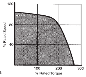 |
Typical shunt-wound motor performance curve |
|
Cautions: |
Reversing the armature
while it is rotating is called “plugging” or
“plug reversal.” Because of the counter electromotive
force (cemf) or generated
voltage in the armature, plugging will subject
the armature to approximately twice
the rated voltage and therefore should be
used with discretion.
Dynamic braking, while not as severe as
plugging, should also be used with caution.
A shunt motor can be dynamically braked
by “shorting” the armature after it has been
disconnected from the line. Current-limiting
resistors are generally used to reduce the
severity of this operation.
Brush life on a shunt-wound motor is
usually good. However, severe duty cycles,
like plugging and dynamic braking,
can adversely affect brush life. Such applications
should be carefully studied to prevent
excessive stress to brushes and other
motor parts. With direct current, an electrolytic
action takes place which causes
one brush to wear faster than the other.
This is a normal condition. The quality of the DC wave shape coming from the control
will also have an important effect on
brush life. Recognizing these precautions
and using a careful and intelligent approach
to shunt-wound motor application will usually
guarantee long and successful brush
and motor life. |
| |
| Permanent Magnet
(PM) |
Features: |
- Continuous duty
- DC power supply
- Reversibility at rest or during rotation
with current limiting
- Relatively constant and adjustable speed
- Starting torque 175% and up of rated
torque
- High starting current, relative to full load
running current
|
Design and Operation: |
Historically,
permanent magnet field motors provide
a comparatively simple and reliable
DC drive in applications requiring high efficiency,
high starting torque and a linear
speed/torque curve. With the great strides
made in ceramic and rare earth magnet
materials, combined with electronic control
technology, the PM motor has taken on a
new importance as an adjustable speed
drive delivering significant performance in a
relatively compact size. See figure below.
The single design feature which distinguishes
the PM field motor from other DC
motors is the replacement of the wound
field with permanent magnets. It eliminates
the need for separate field excitation and
attendant electrical losses in the field windings.
The armature and commutator assembly
in conventional PM motors is similar to
those found in other DC types. |
 |
Permanent magnet motor. |
|
Advantages: |
| Perhaps the most
important advantage of PM field motors is
their smaller overall size made possible by
replacing the wound field with ceramic permanent magnets. For a given field
strength, the PM ring and magnet assembly
is considerably smaller in diameter than its
wound field counterpart, providing substantial
savings in both size and weight. See
figure below. And since the PM motor is not
susceptible to armature reaction, the field
strength remains constant. |
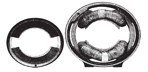 |
Stators for 1/4 hp (186.5 watt) ventilated shunt-wound field DC motor (right)
and 1/4 hp PM DC motor (left). Note that the inner diameters of the two stators are
the same, while the outer diameter of the PM motor is considerably smaller. |
|
| Armature reaction can act to weaken
the magnetic field of a conventional shunt wound
DC motor at loads beyond approximately
200% of rated value. This characteristic
is generally responsible for the
“drop off” in torque associated with shunt wound
designs. See figure below. |
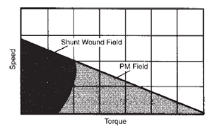 |
Comparison of shunt and PM
motor curve shapes. |
|
If we examine the field construction of
the wound field and PM field motors, we
can explain the differences in armature reaction
and corresponding differences in
speed / torque characteristics of the two
motor types. The armature magnetizing
force in a wound field construction “sees”
a very high permeability (low reluctance)
iron path to follow. In the PM field design,
this armature magnetizing force is resisted
by the low permeability (high reluctance)
path of the ceramic magnet, which tends to
act as a very large air gap. The net result is
that the armature cannot react with the field
in a PM motor, thereby producing a linear
speed / torque characteristic throughout its
entire torque range.
PM motors can be useful in a number of
specific ways:
- They produce relatively high torques at low speeds, enabling them to be used as substitutes for gearmotors in many
instances. PM motors operated at low
speeds are especially useful where
“backlash” and inherent mechanical
“windup” of gearing in gearmotors can
not be tolerated.
- The linear speed / torque curve of PM
motors, coupled with their ability to be
easily controlled electronically, make
them ideal for adjustable speed and
servo motor applications.
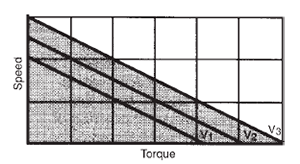
- The linear output performance characteristics
of PM motors also make it
easier to mathematically predict their
dynamic performance. See figure below.
|
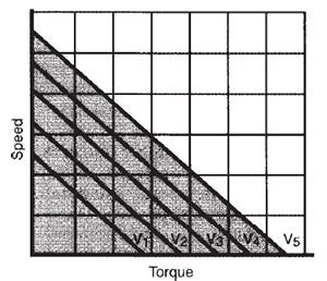 |
A typical family of
speed / torque curves for a PM motor at
different voltage inputs, with V5 > V4 > V3 > V2 > V1. |
|
Since the PM field motor is not affected
by armature reaction, it can produce very
high starting torque. This high starting
torque capability can be a valuable asset in
many “straight motor” (innermost)
applications as well as inertial load applications
requiring high starting torque with less
running torque. PM motors function well as
torque motors for actuator drives and in
other intermittent duty applications.
The size reduction in PM motors is generally
accomplished without any significant
change in the temperature rise rating for a
given horsepower. In fact, the electrical
efficiency of the PM motor is very often
10% to 15% higher due to the elimination
of field copper losses which occur in
wound field motors. PM motors can be
produced in TENV (totally enclosed non ventilated)
construction, eliminating the
need for fans and providing much greater
application flexibility.
With their higher inherent efficiency, PM
motors offer lower current drain for more
efficient battery operation in portable applications.
The permanent magnets also provide
some self-braking (less shaft coast)
when the power supply is removed. PM
motors require only two leads (shunt wound
motors require four). The leads can
be reversed by simply changing the polarity
of the line connection. Dynamic braking is
achieved by merely shunting the two leads
after disconnecting them from the power
source. PM designs also provide similar
performance characteristics to shunt wound
DC motors when used with all
common control methods (except field
weakening). |
Disadvantages: |
While ceramic
magnets now have properties which make
them very reliable, certain characteristics of
these materials must be thoroughly understood
if proper operation of ceramic magnet
PM motors is to be obtained. At lower
temperatures (0°C and below), ceramic
magnets become increasingly susceptible to
demagnetizing forces.
Armature reaction (which is capable of
producing the threshold limit for demagnetization)
takes on greater importance at
lower temperatures. Therefore, special
attention must be given to overload current
conditions including “starting,” “locked
rotor” and “plug reversing” when applying
PM motors to low temperature use. Plug reversing requires current limiting, even at
normal temperatures.
The design of the motor’s power supply
is also important. SCR circuits can be designed
to provide current regulating and /
or limiting features to protect the motor at
low temperatures. The actual application
parameters involved vary with each particular
PM motor design, since the protection
against demagnetization is part of the motor’s
design and must be considered accordingly.
It is best to consult the manufacturer
if low temperature use or plug reversing
is contemplated.
As operating temperature increases, the
residual or working flux of PM motors
decreases at a moderate rate. This flux
decrease is much like the decrease of field
flux strength in wound field motors as copper
resistance increases with temperature.
On a motor-to-motor and lot-to-lot
basis, PM motors are sometimes criticized
for having somewhat greater variability in
performance characteristics than wound
field designs. Such criticism may be the
result of greater variations encountered in
both the quality of the raw materials and
the processes employed in the manufacture
of the magnet segments themselves. However,
undue variation can be greatly minimized
by the motor manufacturer. Proper
magnetic circuit design and calibration of
the magnetic assembly to a predetermined
common field strength value (somewhat
less than full saturation) can do much toward
achieving consistent motor performance.
Too often, calibration is ignored by
some motor manufacturers because of
cost, and in many cases, the variation in the
level of flux achieved by saturation alone is
considered acceptable.
Another concern is whether a PM motor
can be disassembled without loss of
field strength and without having to provide
any additional magnetic circuit keeper. The
answer can be yes and no, depending primarily upon the characteristics of the
magnetic materials selected for a given
design. Although newer ceramic materials
permit disassembly without loss of magnetic
field strength, the user should consult the
manufacturer before attempting to disassemble
the motor. |
Cautions: |
Because of their high
starting torque characteristic, care must be
exercised in applying PM gearmotors. A
PM gearmotor application should be carefully
reviewed for any high inertial loads or
high starting torque loads. These types of
loads could cause the motor to transmit
excessive torque to the gear head and produce
output torque which exceeds its design
limits. SCR controls having current
limiting circuits or overload slip clutches are often employed to protect gearing used
with PM motors. |
| |
| BRUSHLESS DC
MOTOR ACTION |
A segmented commutator rotating
within a stationary magnetic field causes
mechanical switching of the armature current.
In a brushless DC motor, the magnetic
field rotates. Commutation occurs electronically
by switching the stator current
direction at precise intervals in relation to
the position of the rotating magnetic field.
Solid state controls and internal feedback
devices are required to operate brushless
DC motors.
Brushless DC motors combine characteristics
of both DC and AC motors. They
are similar to AC motors in that a moving
magnetic field causes rotor movement or
rotation. They are similar to DC motors
since they have linear characteristics. The figure below shows cross-sections of AC, DC
and brushless DC motors. The AC motor
has windings in the stator assembly and a
squirrel cage rotor. The PM DC motor has
windings on the rotor assembly and permanent
magnets for the stator assembly. The
brushless DC motor is a hybrid of the AC
and DC motors. The rotor has permanent
magnets and the stator has windings. |
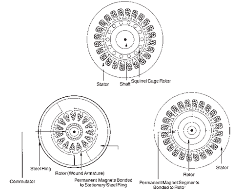 |
Cross-sections of: a) an AC motor (top), b) a PM DC motor (left), and c) a
brushless DC motor (right). |
|
| |
| Brushless DC |
Features: |
- Continuous duty
- DC power supply
- Reversibility at rest or during rotation
with current limiting
- Adjustable speed
- Starting torque 175% and up of rated
torque
- High starting current
|
Design and Operation: |
| Brushless
DC motors consist of two parts: the
motor and a separate electronic commutator
control assembly (see figure below). |
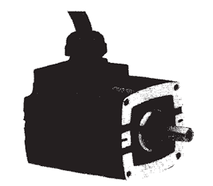 |
Brushless DC motor. |
|
| The two must be electrically connected
with a cable or wiring harness before motor
action can take place. See figure below. |
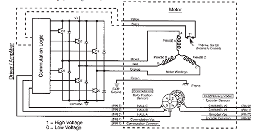 |
Schematic diagram of a brushless DC motor and control. |
|
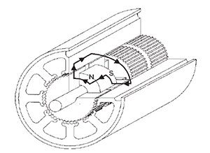
| By energizing specific windings in the
stator, based on the position of the rotor, a
revolving magnetic field is generated. See
figure below. Sensors mounted inside the motor
detect the position of the permanent
magnets on the rotor. For example, as the
rotor moves through a specific angle or
distance, one of the sensors will detect a
change from a north magnetic pole to a
south magnetic pole. |
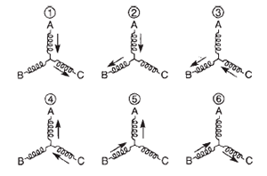 |
Phase current flow. |
|
At this precise instant, current is
switched to the next winding phase. By
switching current to the phase windings in a
predetermined sequence, the permanent
magnets on the rotor attempt to chase the current. The current is always switched
before the permanent magnets catch up.
Therefore, the speed of the motor is directly
proportional to the current switching
rate. At any instant, two windings are energized
at a time with the third one off. This
combines the torques of two phases at one
time, thus increasing the overall torque output
of the motor.
The rotor consists of a four-pole permanent
magnet and a smaller four-pole
sensor magnet. As the sensor magnet rotates
it will activate a series of sensors located
60° apart. The sensors can be photo
sensors, Hall effect devices, magneto resistors
or other devices which monitor the position of the shaft and provide that information
to the controller.
The controller logic circuits contain a
binary decoder which interprets the signals
from the sensors regarding the position of
the permanent magnet rotor. The logic circuit
outputs a specific address which tells a
drive circuit
which windings should be energized.
The rotation of the motor is changed
within the control logic which in turn reverses
the phase energizing sequence. A
toggle switch is usually provided to convert
the logic from clockwise to counterclockwise.
The figure below shows the truth tables
for both clockwise and counterclockwise
commutation. |
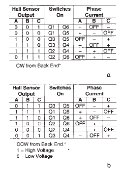 |
Commutation sequence:
a) clockwise (top), and
b) counterclockwise
(bottom). |
|
Trapezoidal vs. Sinusoidal
Torque Properties: |
Timing of the
"on' and "off" switching of different phase
pairs is determined by the signals emanating
from the sensors in the motor's commutation
circuitry.
Trapezoidal torque characteristics of the
phase pairs mean that fewer commutation
signals are required than for a motor whose
phases exhibit sinusoidal torque properties.
This simplifies the control design and minimizes
its cost, while providing a motor
torque output with low ripple properties.
Commutation circuitry is designed to
switch as the torque output and the back
emf in the individual phase pairs reach their
maximum (and most constant) level. This
produces the least ripple effect on the output
torque and the lowest phase current
swing. The resulting smooth output torque
makes it easier to implement digital and
pulse width modulation control techniques. |
Advantages: |
Brushless motors are
more reliable. They do not have commutator
or brushes to wear out. The commutation
is achieved through reliable solid-state
circuit components, making them ideal for
applications where downtime is critical or
where drive system access is difficult. Brush sparking and associated RFI are
eliminated.
Brushless motors are not sensitive to
harmonics like AC motors. The brush
noise associated with brush type DC motors
and commutators is also eliminated.
Brushless DC motors provide predictable
performance because of their linear
characteristics. See figure below. They can
exhibit high starting torques, precise positioning
capability and controlled acceleration
and deceleration. And more power
can be achieved from a smaller size motor.
Brushless motors can be designed with
low rotor inertia. This means they accelerate
more quickly in less time and offer less
power dissipation during the stop / start
cycle. They are also capable of operating
at high speeds since there are no mechanical
commutator limitations. |
 |
Typical speed / torque curve
for a brushless DC motor. |
|
Disadvantages: |
Unlike conventional
DC motors, electronically commutated
designs cannot be reversed by simply
reversing the polarity of the power source.
Instead, the order in which the current is
fed to the field coil must be reversed. Also,
due to low friction inherent in brushless
motors, excessive coasting may be a problem
after the current has been removed.
Special damping circuits or other devices
may be added to remedy this factor, but
cost will be adversely affected.
From a cost standpoint, the electronics
needed to operate brushless DC motors
are relatively more complex and therefore
more expensive than those used with conventional DC motors. While electronically
commutated DC motors are now closer to
being competitive with conventional DC /
tachometer feedback units, they are still
costly when compared with conventional
DC / SCR control drives. |
| |
| Stepper Motors |
Features: |
- Continuous duty
- DC power supply
- Reversibility at rest or during rotation
- Adjustable speed
- Normal starting current
|
Design and Operation: |
The
widespread acceptance of digital control
for machine and process functions has generated
a growing demand for devices that
translate digital commands into discrete
incremental motions of known accuracy.
The ability to interface stepping motors
with microprocessors and / or mini-computer
controls has enhanced their application
potential (see figure below). |
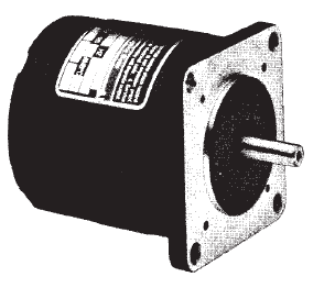 |
Stepper motor. |
|
While conventional AC and DC motors
operate from continuously applied input
voltages and usually produce a continuous
(steady state) rotary motion, stepper motors
move in discrete steps (increments).
Stepping occurs in strict accordance with
the digital input commands provided. At very low stepping rates, the stepping action
at the motor shaft may be visible. At high
stepping rates, the shaft appears to rotate
smoothly, like a conventional motor. Step
error is non cumulative. The absolute
position error is independent of the number
of steps taken. Final shaft position is
predictable within a maximum error
determined by mechanical tolerances, and
from the motor’s static torque vs. angular
displacement curve.
Although we refer to the angular position
of the stepper shaft as the motor’s
“output,” there are many applications
where this rotation is converted to precise
linear motion, for example, by means of the
lead screw or rack and pinion.
DC steppers are divided into three
principle types, each having its own
unique construction and performance
characteristics:
- variable reluctance (VR),
- permanent magnet (PM), and
- PM hybrid.
|
Variable Reluctance: |
Generally
a lower priced drive, the variable reluctance
stepper has a wound stator and a
multi-poled soft iron rotor. The step angle
(determined by the number of stator and
rotor teeth) varies typically from 5 to 15
degrees. Unlike the hybrid design, variable
reluctance steppers have relatively low
torque and inertia load capacity. They are,
however, reasonably inexpensive and adequate
for light load computer peripheral
applications. Operating pulse rates vary
over a wide range, depending upon the
specific design and construction of a particular
motor. |
PM Steppers: |
| With step angles
ranging from 5 to 90 degrees, PM steppers
are low to medium-priced units with typically
slower step rates (100 steps / second
for larger units and 350 steps / second for
smaller ones). They usually employ a wound stator with a PM rotor delivering
low torque. Step accuracy is ≥ ±10%. |
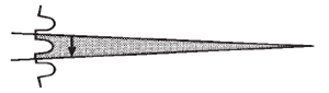
PM Hybrid: |
The PM hybrid stepper
combines the construction and performance
aspects of both PM and variable
reluctance type stepper motors. Both the
rotor and wound stator are toothed. The
toothed rotor is composed of one or more
elements known as stacks. See figure below.
Each stack has both hollow and solid laminations
bonded together to form two cup shaped
structures. A permanent magnet is
inserted in the space between the two
cups. Rotor stacks are then fastened to a
nonmagnetic (usually stainless steel) shaft. |
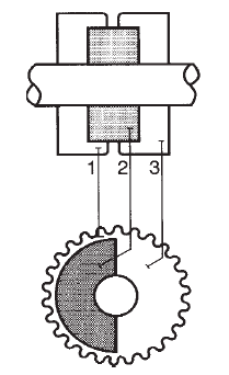 |
1) Hollow laminations,
2) Alnico permanent magnet, and
3) solid laminations. |
|
| nonmagnetic (usually stainless steel) shaft.
The perimeter of each lamination has
multiple teeth with a specific tooth pitch
(angle between tooth centers) depending
on the degree of step required. Step angles
vary from 0.5 to 15 degrees. See figure below. |
 |
PM hybrid stepper tooth pitch. |
|
When the cups are pressed on the shaft
to form a stack, they are positioned in such
a way that the teeth of one cup line up with
the slots of the other cup. The two cups of
each stack are said to be offset from each
other by half of one tooth pitch.
The stack configurations can vary.
When more than one stack is used, nonmagnetic
spacers are inserted between
stacks to prevent coupling. See figure below. |
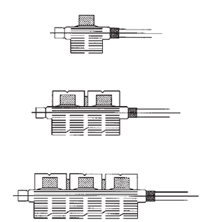 |
Variable stack lengths for PM
hybrid stepper motors. |
|
Without the spacer, the separate magnetic
structures would combine, eliminating the
advantage of multiple stacks. With adequate
space between them, magnetic flux
will follow the path of least resistance
through the stator core, multiplying the
available torque by the number of stacks.
This construction gives the PM hybrid
higher torque capacity (50 to 2000 + oz in.)
with step accuracies to ±3%. See
figure below. |
 |
Flux path through rotor and stator. |
|
The figure below shows a cross-section of a
typical DC PM hybrid stepper with
toothed rotor and stator. When the rotor is
inserted into the stator bore, only one pair
of stator poles will line up exactly, tooth for-
tooth, with the teeth on a single rotor
cup. The remaining poles will be out of
alignment by some fraction of a tooth pitch.
This misalignment is what makes it possible
for a stepper to develop torque. Most PM
hybrid steppers have four phases which are
bifilar wound, but other phase arrangements
and multiples are available.
When phases are energized in a specific
sequence, PM hybrid steppers deliver specific
angular output motions (steps) of
known accuracy, provided that system inertia and friction do not exceed acceptable
limits. |
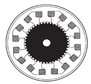 |
Cross-section of a typical DC
PM hybrid stepper with toothed rotor and
stator. |
|
Each angular displacement ends in a
well-defined position of magnetic attraction
called a detent position. These stable equilibrium
positions are created by the magnetic
interaction between the permanent
magnet rotor and the magnetic field produced
by the energized phase windings. As
the motor is stepped, the detent positions
shift around the entire 360° rotation. The
direction of rotation is determined by the
phase energization sequence.
PM hybrid designs offer excellent speed
capability1000 steps / second and higher
can be achieved. Because the step angle
is fixed by the tooth geometry and step
error is non cumulative, the shaft position of
a motor loaded within its capacity is always
known within a fraction of one step. This
open-loop operation eliminates the need
for encoders, tachometers and other feedback
devices which add to system cost. |
Advantages: |
Steppers are popular
because they can be used in an open-loop
mode while still offering many of the desirable
features of an expensive feedback
system. Hunting and instabilities caused by
feedback loop sensitivity and phase shifts
are avoided.
Due to the non cumulative nature of
stepper error, step motors also offer improved
accuracy. The replacement of less
dependable mechanical devices, such as
clutches and brakes, with step motors provides
considerably greater reliability and
consistency. Predictable and consistent
performance coupled with reasonable cost
make the DC stepper an excellent positioning
drive. |
Disadvantages: |
Stepper motors
can be made to produce reasonably high
torques (2000 oz-in. or more). However,
they do have a limited ability to handle extremely
large inertial loads. See Fig. 3-24.
Since steppers tend to oscillate (ring) upon
stopping, some sort of damping means is
usually required. Stepper motors unfortunately
are also not very energy efficient, but
this is the price that must be paid to
achieve the truly unique performance characteristics
available from the stepper motor.
Resonance is sometimes a problem
that can be remedied by a specialized electronic
control design or by avoiding operation
within the step rate ranges prone to
resonance. |
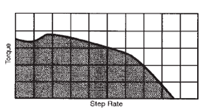 |
Typical torque vs. speed
(steps / second) for a PM hybrid stepper |
|
Constant Horsepower: |
| This
type of load absorbs the same amount of
power regardless of the speed. |
Variable Torque: |
| Some loads
require different torque at different speeds. |
Load Inertia: |
| The load inertia is
expressed as: |
 |
| where M is the mass of the rotating parts
and k is the radius of gyration. |
Acceleration Time: |
| The difference
between the friction torque required
by the load and the torque delivered by the
drive will affect acceleration time. Greater
accelerating torque decreases the time required to get the load to full speed. It can
be expressed as: |
 |
where:
t = accelerating time (seconds)
n2 = final speed (RPM)
n1 = initial speed (RPM)
Ta = accelerating torque (lb-ft.)
available from the drive
(Tdeveloped - Tfriction)
W = weight of rotating system (lbs.)
k = radius of gyration (ft.) |
| |